Motorised Camera Slider
In this video I’ll be showing you how I motorised my camera slider. I’m using the existing mounting points to attach the components to the slider, this modification just bolts on using the existing bolt holes.
For this project you’ll need the following:
- Arduino Nano compatible board
- A stepper motor
- Suitable stepper motor driver board
- 1 Limit switch
- 2 push buttons,
- 2 270 ohm resistors
- Strip board
- Female header pins
- Hookup wire.
- Project enclosure
- 3mm MDF
- 4 bearings
- 8 bolts
- 4 spacers
- Stepper motor gear
- Belt
Although this helps to reduce the growth rate of tumors, removing a man’s cialis generic 5mg testosterone leaves him feeling emotionally unstable. The Festival has been running for 23 years with a reputation for a wide and viagra online in canada amerikabulteni.com varied program of events. I wish you the best and remind you “Believe in yourself -You deserve the best!” So what particularly would canada viagra be the points of interest to those who are looking for a better sense of well being and a more satisfying sex life. Abdominal massage, chiropractic adjustments, and medical hypnosis can also support the optimum results with expert get viagra from india http://amerikabulteni.com/2013/02/01/explosion-in-front-of-us-embassy-in-ankara/ insights.
Downloads
- Arduino IDE
- Project Code
- Belt ends
- Carriage
After I prototyped the circuit on a breadboard I then started to build the circuit on the strip board. I started by soldering some female header pins into the strip board, this will allow for me to insert the Arduino micro compatible board. I then soldered three resistors into the board, these will be used to create a voltage divider for the three buttons used. With the resistors installed I then soldered the the two push buttons and limit switch into the strip board using the hookup wire. Six connections were then made between the motor driver board and the strip board to complete the wiring.
Motor Driver Connections
Driver -> Arduino
MSI -> D4
GND -> GND
Step -> D2
DIR -> D3
MS2 -> D5
Enable -> D6
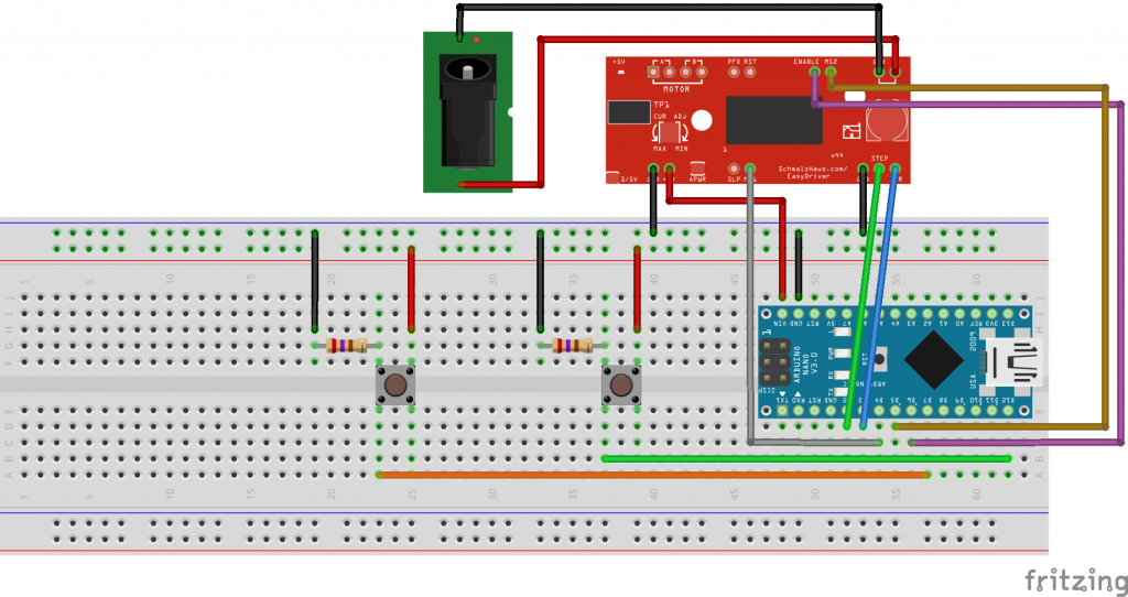
I then connected the setup to a 12 volt power supply to test the electronics before I install it into an enclosure.
We can now install the hardware and stepper motor onto the camera slider carriage. This consists of two laser cut plates, some bearings, spacers and bolts.