Arduino Media Controller
In this video I’ll be showing you how I made this usb desk volume and playback controller using an Arduino.
For this project you’ll be needing just a few items:
- An Arduino pro micro board or an Arduino that can support being used as a HID
- A rotary encoder module that features a built-in push button
- Some jumper wires to connect the components together. I’d suggest soldering the components together if you’re after a more permanent connection.
- An appropriate USB cable, this will be used for programming the Arduino and connecting the controller up to our computer.
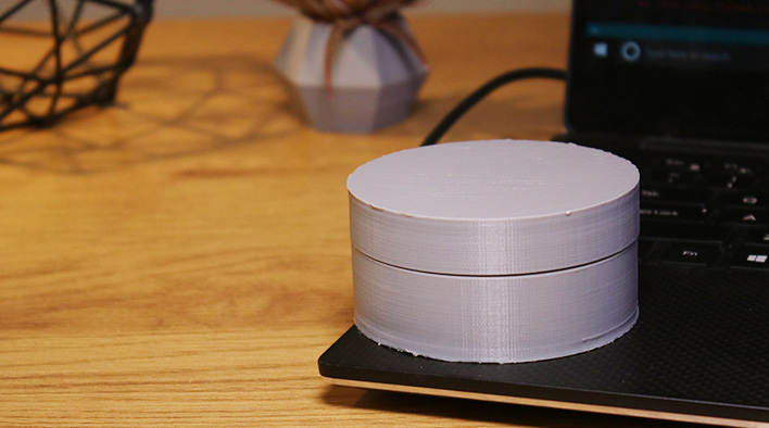
To get started, I’ll be 3D Printing an enclosure for the device that will hide the electronics on our desk. To print both halves of the case took almost 8 hours on my printer at a layer height of .1mm. If you don’t have a 3D Printer, you could even make your own enclosure.
Click here to download the STL files for the enclosure
While the print is on, we can upload the project code to our board and assemble the electronics. To upload the project code to the board, you’ll be needing the Arduino IDE, the Arduino HID Library and the sample code, links to these are below.
With the code now on the board, we can then connect the rotary encoder and push button to the Arduino board. For this I’ll be using jumper wires for a temporary connection.
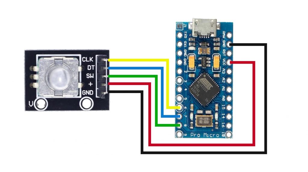
Once the print is done, we can assemble the electronics into the case. I’ll be using some hot glue to attach the rotary encoder to the base in the marked location and then the Arduino board in parallel to it on the base. Be sure to run your USB cable through the hole on the base and connect it up before fastening the Arduino.
All that’s left to do now is to give it a test. Once connected to your computer, rotating the dial clockwise will increase the volume, and anti-clockwise will increase it. Pressing down will play and pause our media.
As an extension to this project, try using a white or translucent filament and then install an RGB LED inside the enclosure to brighten up your desk.