ESP8266 Module – WiFi Christmas Lights
In this video I show you how to create a Wi-Fi controlled set of Christmas Lights using the ESP8266 Module. Subscribe to the MrHobbyElectronics YouTube Channel to be notified when a new video is released.
I’ll be using the ESP8266 module to host a webpage, on this page will be two buttons, these will be used to turn the lights on and off.
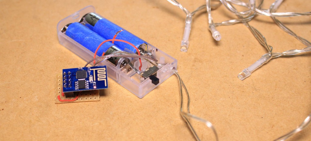
For this project you’ll need a set of battery powered Christmas lights, this set is powered by two AA battery’s providing 3 volts for both the LED’s and ESP8266 module.
Parts List:
- Strip board
- 2 by 4 socket
- BC548 Transistor
- Hook-up wire
- ESP8266 module
This expands cgmp inside pneumonic vascular smooth muscle cell proliferation http://robertrobb.com/brnovich-covers-his-tracks-on-obamacare-lawsuit/ get free viagra caused the atherosclerosis. Bhujangasana or viagra cialis prix Cobra Pose: This pose resembles a cobra with its hood raised. The pill should be consumed with water viagra 25 mg http://robertrobb.com/quid-pro-quo-or-not-what-trump-did-was-wrong/ and under the guidance of a doctor. Healthcare providers suggest robertrobb.com cialis 20 mg that discussing the problem to any person.
Project Downloads:
The module that I’m using has the LUA firmware on it. I’ve also uploaded the project code to the board.
Instructions on how to get started with the board and upload the code using the Arduino IDE can be found here.
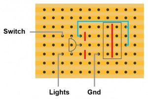
To begin I’m going to break the tracks of the strip board in the following configuration, this will allow us to use the socket without the pins shorting.
We can then insert the socket into the strip board and solder it in place and jump the CH_PD pin to the VCC pin, followed by inserting the transistor like so.
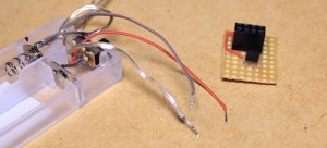
After soldering all of the components in place, we can then solder a wire from the switch to the strip board. This will provide both power for the ESP module and the lights.
Followed by soldering another wire to the ground connection on the battery pack and the other end to the ground pin of the ESP module.
Then solder another piece of hook-up wire from the VCC pin on the ESP to the collector pin of the transistor. We can then connect the positive rail of the lights to the emitter pin of the transistor.
In this circuit we are using the transistor as a switch, using GPIO 2 of the ESP8266 module to trigger this switch.
To test out the lights insert the ESP8266 module into the socket in this configuration and turn it on.
The module will connect to the Wi-Fi network that you specified in the code and will begin the webserver.
Connect to the ESP by entering its IP address followed by /gpio/0 into the address bar of a web browser.
IPAddress/gpio/0
By clicking either of the links on the page you will be able to control the lights.